

 Deutsch
Speaker assignment for eMOTION sound decoders
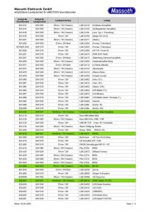
Current list of speaker assignment for eMOTION sound decoders (german only) Date: 03. April 2020

Current list of speaker assignment for eMOTION sound decoders (german only) Date: 03. April 2020
Sorry, this entry is only available in German.
Sorry, this entry is only available in German.
Sorry, this entry is only available in German.
As always the question arises, how to digitize a Ge 4/4 III with pantograph control, enclosed in the picture the necessary additional parts: 1 x Onboardadapter 8150701 1 x SUSI – LGB Onboard 4-wire 200mm 8312075 1 x Special Adapter cable 1 wire as shown in the picture. In case of need you can also cut the plug and connect the 1 cable as shown in the picture to…
Enclosed is the connection diagram of the Massoth LS decoder and the 10-pin DCC interface. LS_an_DCC_Schnittstelle.pdf
The maximum length of the bus cable depends on the cable used! For a non-shielded telephone cable, it is a maximum of 20m. For a CAT 5 or CAT 6 cable the length is almost unlimited. Whereupon a special bus amplifier is needed.
Connection of the Reverse loop module in an oval.
Stop in a single siding track As an example for a train stop in a single siding track or station. Additionally on pull in or out the bell will start from the decoder Note: In this example we use a signal, that doesn’t exist. You don’t need a signal to use the functions! Please program the IR-Sender as follows: CV 32 = 5 (Address of the signal) CV 41 =…
Simple Shuttle operation with two stops As an example we will describe here a simple shuttle operation with two end points. The locos will stop in the station and will start after a fixed time. Please program the IR-Sender 1 as follows: CV 32 = 1 (Address of the signal) CV 41 = 5 (Automatic) CV 42 = 4 (Shuttle forward) CV 45 = 15 (15 Sec. stop) Activate it…
Here we wan’t to describe the Reset address (CV31+32). You can set this in the IR Receiver. Following example: You drive on your layout until the signal red, the locomotive stops. You take your locomotive off the track and pack it up. At a guest layout you put your locomotive on the track, but the locomotive is blocked by a red signal from the previous trip! Now you need…
Here you can find a list of supported decoders for our Infrared System Decoder Function CV Minimum firmware Decoder with SUSI BIDI eMOTION LS SUSI-BIDI CV 49 Value+16 4.1 eMOTION XLS SUSI-BIDI CV 49 Value+16 4.1 eMOTION XLS-M1 SUSI-BIDI CV 49 Value+16 4.1 eMOTION XLS-OnBoard SUSI-BIDI CV 49 Value+16 4.1 eMOTION XL-M1 SUSI-BIDI CV 49 Value+16 eMOTION XL II Plug SUSI-BIDI CV 49 Value+16 eMOTION XXL II SUSI-BIDI CV…
Here we want to describe the control of the IR receiver via the contact inputs of the decoder. If your decoder does not have a SUSI-BIDI interface (see here), you can still use our infrared system. Automatic or switching functions are not possible here. Connect the receiver as shown below. As an example, an XL decoder was chosen. In the IR receiver, set CV 62 to 2 to activate…
Description of the Block signal mode with our IR System. You need additional Track Contacts and a Feedback module. Input A set the signals to red, input B set the signal to green. The last contact (4) has a special function. He releases the block signal again. If your block signal layout is a circle, you can remove the last contact. Therefore you have to connect 1A with 3B….
Sometimes the elimination of radio problems can be very easy. The cause is sometimes “animal nature” as you can see in the picture. Here ants have disturbed the Massoth Bus by being run through the contacts. The voltage meant Unfortunately for the ants to death. Since the ants are still at the contacts, thereby the signal is still disturbed. After cleaning the contacts, everything should work again.
Identification of the decoder when installed Often you have the problem with a hand purchased loco, not knowing what decoder is installed. There is some advice on how to get information about it. As an example using our navigator in CV reading mode You can identify the manufacturer in CV 8. Based on the value you can then assign the manufacturer. Below is a list of the most common…
For a turntable you have to connect a Reverse Loop Module. In this sketch you can see how to connect.
Here we would like to briefly explain what reinforced and unreinforced switching outputs of our decoders are. Below is a drawing that explains how the outputs work (As an example with a XLS): A reinforced output is connected between + 22V and the switching output. If the switching output is turned off, there is +22V output, therefore is no potential difference is and no current flows. If the switching…
Attached you can find a manual how to connect the decoupler to OnBoard small with programming. Entkuppler_an_LGB_OnBoard_klein.pdf
Attached you can find the connection diagram of the big LGB Onboard Decoder. Uncoupler 1 will be connected normally. Uncoupler 2 cut off the plug and connect red to + F2 brown to – F2 black to black of decoupler 1 You have to decide whether you want to dispense with the smoke unit. Programming: CV49=32 CV56=32 CV51= 1-8 (Desired button F1) CV57= 1-8 (Desired button F2) LGB-ZD-3A-komplett.pdf

Optimized Email Structure for Even More Efficient Customer Service…
With the newly released Version 1.2, the DiMAX LED…
