

 Deutsch
Here we would like to briefly explain what reinforced and unreinforced switching outputs of our decoders are.
Below is a drawing that explains how the outputs work (As an example with a XLS):
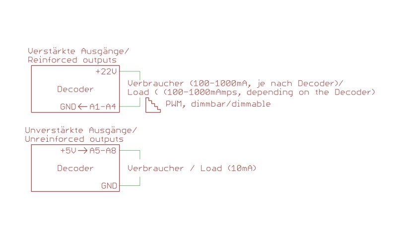
A reinforced output is connected between + 22V and the switching output.
If the switching output is turned off, there is +22V output, therefore is no potential difference is and no current flows.
If the switching output is turned on there is GND at the output, so the load has full voltage.
Dimming is based here by PWM (Pulse Width Modulation).
An explanation can be found here.
An unreinforced output is connected between switching output and GND.
If the switching output is turned off, there is GND at the output, therefore is no potential difference is and no current flows.
If the switching output is turned on there is +5V at the output, so the load has full voltage.
These outputs can be loaded only up to 10mA. Therefore not suitable for light bulbs.